Web Platform
3.1) Web: Spots creation and Configuration
Updated at 4/26/2023
A Spot (monitoring point) can be created directly within a machine, subset or component.
To start creating, simply select the “![]() ” option in the Asset Tree, followed by the “create” button, represented by the “
” option in the Asset Tree, followed by the “create” button, represented by the “![]() ” icon, at the desired level.
” icon, at the desired level.
Finally, you must select the option to create Spot through the “ ” icon.
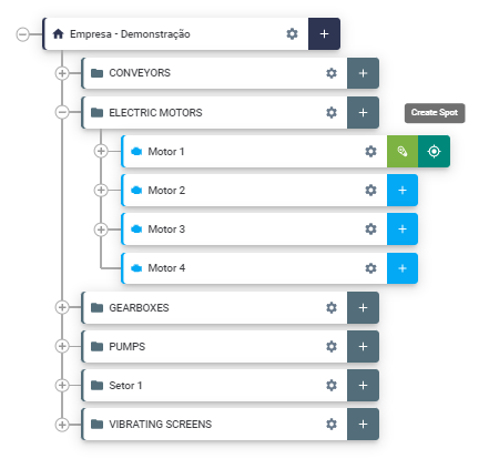
Figure: Spot Criation
After the creation, a new registration drawer, with configuration steps will be presented.
First, it is necessary to add the Spot identification, that is, the name given to the monitoring point. Then, you must choose the sensor model that you want to register in this point: TcA+, TcA, AS, HF, RE, HF+, TcAg or TcAs. (Information available in the body of the DynaLogger).
*Note: To effectively associate a DynaLogger to the refered Spot, it is necessary to access the mobile application since the sensor communicates via Bluetooth. For further information about associating a sensor to a Spot, please refer to the DynaPredict Application Manual, Predictive module.
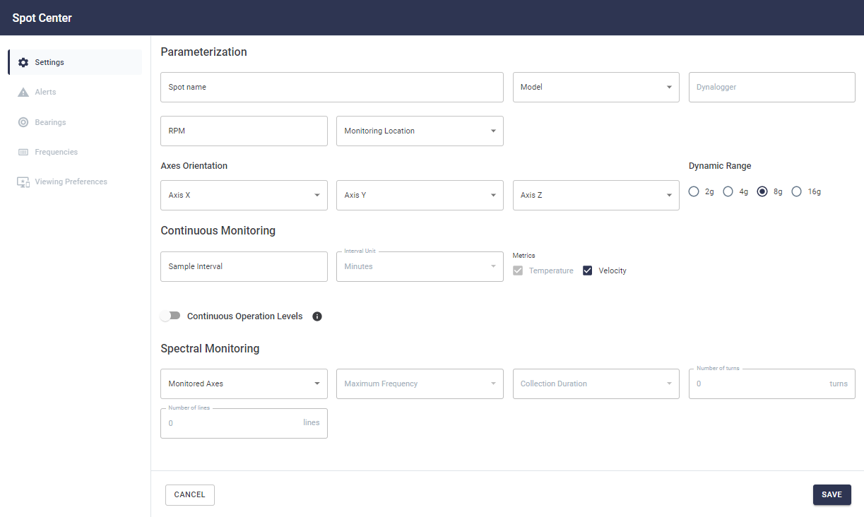
Figure: Spot Information Tab
– RPM: rotations per minute of the closest rotating component to the mounting location of the chosen sensor.
– MONITORING LOCATION: Type of component/equipment to which the DynaLogger will be attached to.
– AXIS ORIENTATION: defines the positioning orientation of the DynaLogger that will be installed. The fixed orientation of the DynaLoggers is displayed on the body or label of the devices. Based on this orientation, the user must select the actual positioning given to the DynaLogger installed referring to the machine.
– DYNAMIC RANGE: parameter that delimits the maximum vibration level that can be measured by the DynaLogger. The 4 options are ±2g, ±4g, ±8g and ±16g. This item is important for quality measurement. An incorrectly chosen dynamic range may result in saturation of the signal or loss of resolution and measurement quality. We recommend selecting the lowest value that comprises the normal vibration of the machine, and leaving a certain margin in case that any amplitude evolves. For example, the appearance of a defect in the monitored component. More information in “How to choose the dynamic range”
– CONTINUOUS MONITORING: the sample interval parameter is the value that defines how often will the DynaLogger turn itself on and collect vibration and temperature measurements. These measurements will be stored in the DynaLogger’s internal memory and will be waiting for collection via application or gateway.
This will later generate a data history that is accessible on the Web Platform.
The complementary item “Metrics” defines which magnitudes will be collected at each sample interval configured above.
Note: any value from 1 to 60 min is available for selection in the sample interval field.
– SPOT OPERATION LEVELS: This setting is optional and serves to register the machine’s hour meter in operation or under stress, that is, based on the machine’s vibration levels, the system counts the operation time in each situation. To use this option, simply activate the symbol and, in metrics, choose between velocity and acceleration. Then you must select the axis that you want to monitor (or all axes) and enter minimum operating thresholds, i.e. below which level the machine will be considered turned off. The user may also define a maximum stress threshold, above which machine will be considered in stress operation.
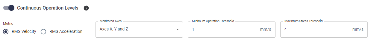
Figure: Stressed and Stopped Machine Configuration Levels
This is important for Spots that will be collected later by gateways or Spots that will be collected by different inspectors via App, because a collection pattern will be generated. This pattern makes the analysis more assertive and afterwards vibration analysts will make the predictive reports.
The “Monitored Axes” option determines the axes to be collected. It’s possible to select the unixial or triaxial collection option, as shown in the image below.
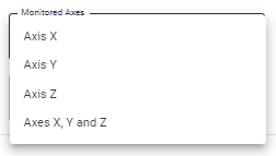
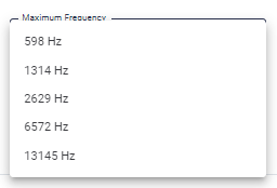
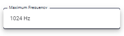
Figure: Max. frequency options
The number of turns and the number of lines will change according to the choices in the fields above, and the rpm determined at the point. Below there’s an example for the case of RPM = 2400.
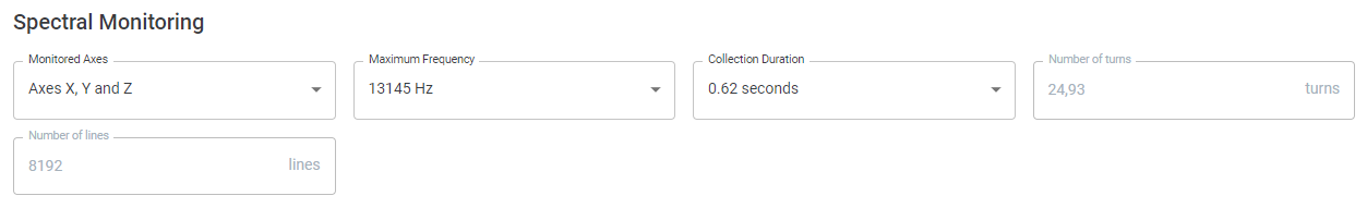
Figure: No.of turns with the chosen 13145 Hz, 0.62s, 2400 RPM configuration.
Remember that this process only creates the monitoring point (Spot). To actually start getting vibration and temperature data from this location, you must perform the physical installation of the DynaLogger and associate the corresponding serial number via mobile app.
Note: the only mandatory tab to be filled in when creating spots is precisely the one described in this article. The others (Alerts, Bearings, Frequencies, and Viewing Preferences) are important, but are optional and can be done in a second moment, that is, they do not require pre-installation of the sensor on field.
Back to articles